
Máy hiện sóng Tektronix TBS1104, 100MHz, 4CH, 1GSa/s
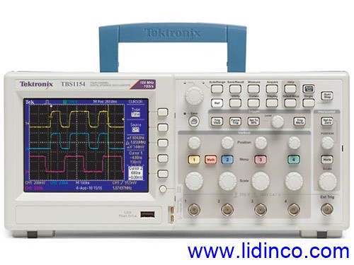

Máy hiện sóng Tektronix TBS1104, 100MHz, 4CH, 1GSa/s
Mã:
TBS1104
Thương hiệu:
Bảo hành:
N/A
Giá: Liên hệ
- Băng thông:
- Tốc độ lấy mẫu:
- Chiều dài sóng:
- Số kênh đo:
- Vui lòng liên hệ để kiểm tra tình trạng kho
- Tạm thời chưa có khuyến mãi cho sản phẩm này
Hotline: 0906.988.447
Liên hệ: Hồ Chí Minh
- Điện thoại: (028).3977.8269
- Email: sales@lidinco.com
- Địa chỉ: 487 Cộng Hòa, Phường 15, Quận Tân Bình, TP. HCM
Liên hệ: Bắc Ninh, Hà Nội
- Điện thoại: (0222).730.0180
- Email: bn@lidinco.com
- Địa chỉ: 184 Bình Than, Phường Võ Cường, TP. Bắc Ninh
 Tư vấn kĩ thuật Miễn phí
 Miễn phí vận chuyển Đơn hàng trên 3 triệu
Thông số kỹ thuật
- Băng thông: 100MHz
- Số kênh: 4 kênh
- Tốc độ lấy mẫu: 1GSa/s
- Độ dài bản ghi điểm: 2.5k point
- Trigger: Pulse width, video
- 16 chức năng đo tự động, phân tích FFT
- Tính năng ghi, lưu trữ dữ liệu
- Hỗ trợ đa ngôn ngữ
- Màn hình TFT 5.7 inch
- Trọng lượng: 2,4kg
- Kết nối: USB 2.0 trên mặt trước để lưu trữ dữ liệu nhanh chóng, dễ dàng
- Cổng 2.0 ở mặt sau để kết nối với PC hoặc máy in
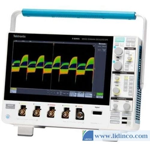
Giới thiệu máy hiện sóng Tektronix TBS1104, 100MHz, 4CH, 1GSa/s
Máy hiện sóngTektronix TBS1104 với băng thông 100MHz, 4 kênh đo là dòng máy hiện sóng chất lượng cao được nhiều phòng thí nghiệm, nghiên cứu, trường đại học sử dụng
Tính năng, đặc điểm của Tektronix TBS1104
- Băng thông: 100MHz
- Số kênh: 4 kênh
- Tốc độ lấy mẫu: 1GSa/s
- Độ dài bản ghi điểm: 2.5k point
- Trigger: Pulse width, video
- 16 chức năng đo tự động, phân tích FFT
- Tính năng ghi, lưu trữ dữ liệu
- Hỗ trợ đa ngôn ngữ
- Màn hình TFT 5.7 inch
- Trọng lượng: 2,4kg
- Kết nối: USB 2.0 trên mặt trước để lưu trữ dữ liệu nhanh chóng, dễ dàng
- Cổng 2.0 ở mặt sau để kết nối với PC hoặc máy in
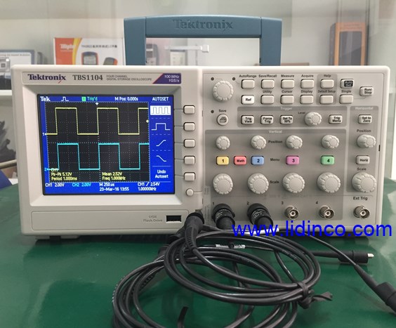
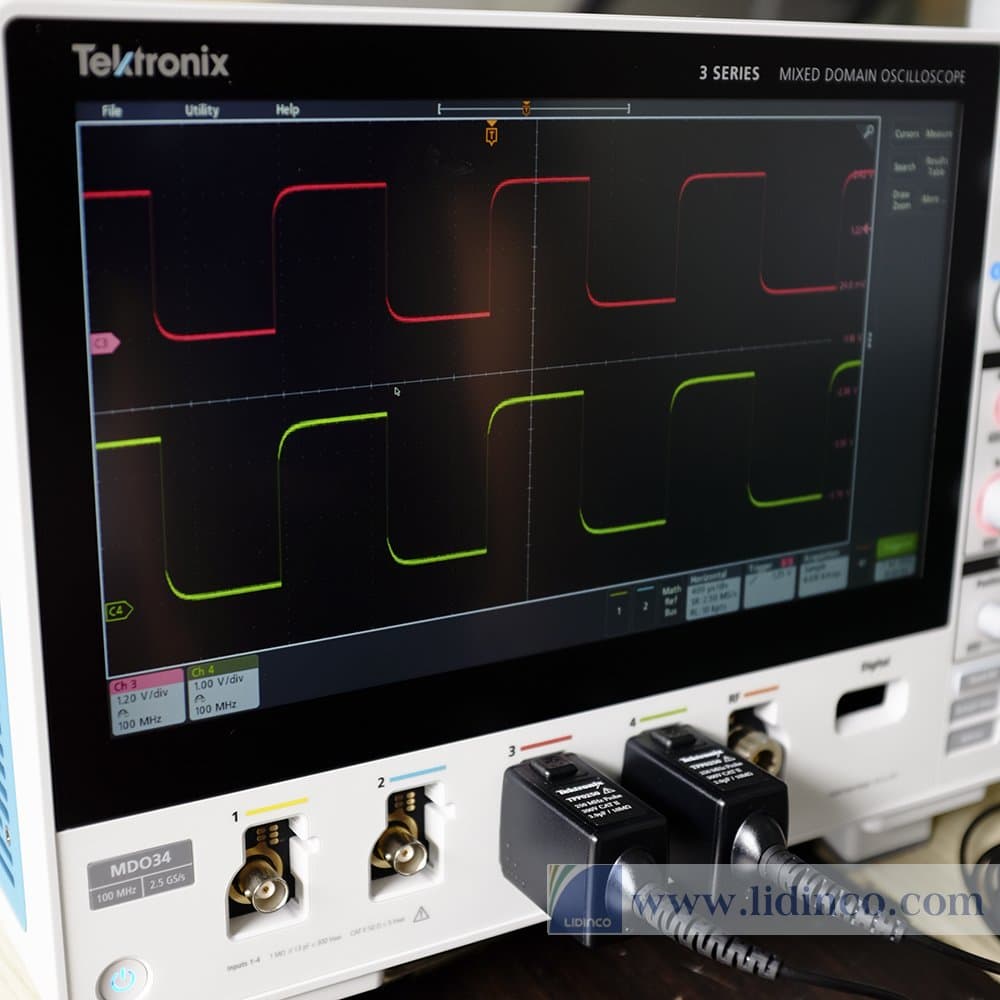
Hình thực tế máy hiện sóng TBS1104 tại Lidinco
Specifications

Phụ kiện

Thông số chính
- Băng thông:
- Số kênh đo:
- Tốc độ lấy mẫu:
- Chiều dài sóng:
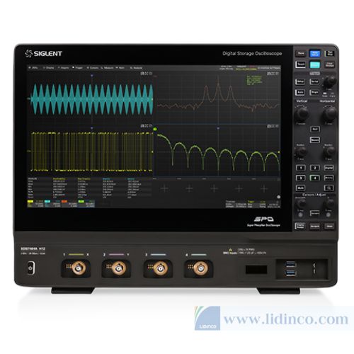
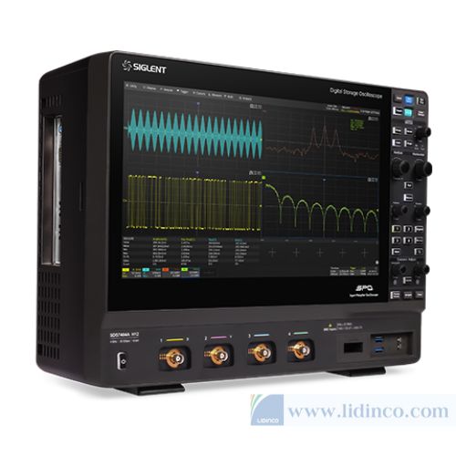
Máy hiện sóng Siglent SDS7604A H12
Liên hệ
Thông số chính
- Băng thông:
- Số kênh đo:
- Tốc độ lấy mẫu:
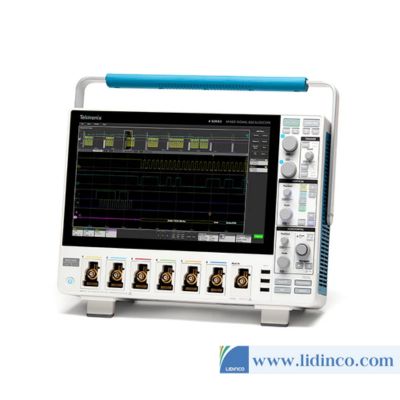
Máy hiện sóng Tektronix MSO46B 1.5GHz 6 kênh
Liên hệ
Thông số chính
- Băng thông:
- Số kênh đo:
- Tốc độ lấy mẫu:
Máy hiện sóng Tektronix MSO44B 200MHz - 1.5GHz
Liên hệ
Thông số chính
- Băng thông:
- Tốc độ lấy mẫu:
- Chiều dài sóng:
- Số kênh đo:
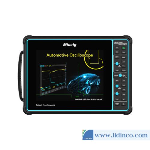
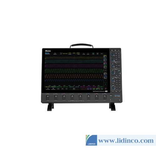
Máy hiện sóng độ phân giải cao Micsig MHO68-350
Liên hệ
Thông số chính
- Băng thông:
- Tốc độ lấy mẫu:
- Chiều dài sóng:
- Số kênh đo:
Máy hiện sóng độ phân giải cao Micsig MHO68-500
Liên hệ

Thông số chính
- Băng thông:
- Số kênh đo:
- Tốc độ lấy mẫu:
Máy hiện sóng Tektronix MSO46B 1.5GHz 6 kênh
Liên hệ
Thông số chính
- Băng thông:
- Số kênh đo:
- Tốc độ lấy mẫu:
Máy hiện sóng Tektronix MSO44B 200MHz - 1.5GHz
Liên hệ
Đánh giá & nhận xét
Vui lòng đăng nhập để viết đánh giá!